

ESP32 Measuring voltage with maximum precision
This is a complete guide of measuring voltages with ADC pins of the ESP32 microcontroller. Precision measurements are very important to us, because our future experiments and hardware development efforts will depend on it
IntroCopy permalink to clipboard
At the beginning before we start , I would like to point something out. It is about small differences between different ESP32 development kits. For this example we are using ESP32 DOIT DEVKIT V1. Your results may be different and if they are please let us know @BromleySat and we can include new findings in this article
Relevant linksCopy permalink to clipboard
Example Source Code (without the use of Kasia IoT)
Hardware setupCopy permalink to clipboard
For now we will start with an ESP32 and a battery (this one is AA alkaline and is no longer usable but still has a low charge). We will also use a voltage divider to measure the battery voltage.
This is a commonly used voltage divider with R1 resistance of R1 = 30kΩ and R2 = 7.5kΩ This gives us a 5 times voltage multiplier so that for every 5 volts increase in the real voltage, our measured voltage will increase by 1 volt. If you want to find out exactly why the multiplier is 5, you can read the details the Voltage Divider Multiplier section
To trace down some of the inaccuracies, we will use a potentiometer If you will choose to follow the example with the use of Kasia IoT, then you will need a mobile phone and a power supply this allows us to conduct tests without the need to be constantly connected to a laptop
You need to connect the negative from the voltage divider to GDN of ESP32. The positive gets connected to and ADC1 pin GPIO32 to GPIO39
The opposite side of the voltage divider has GND and VCC pins that are connected to the screw terminal. You need to connect two wires there and they can be used as your voltage probe

ESP32 Measuring Battery Voltage Hardware Setup
Easy start with Arduino IDECopy permalink to clipboard
Lets start with the simplest approach that is often described online, primarily because a lot of ESP32 users have started on an Arduino and it makes it easier to explain. You can create a new sketch in Arduino IDE and copy paste this code there:
  const int voltagePin = 32;
  float analogValue = 0;
  float voltage = 0;

  void setup() {
    Serial.begin(9600);
  }

  void loop() {
    analogValue = analogRead(voltagePin);
    voltage = map(analogValue, 0, 4095, 0.0, 2500.0); //deliberate mistake ;)
    voltage /=100;

    Serial.print("voltage ");
    Serial.println(voltage);
    delay(500);
  }
Please note that we cannot simply map it directly to the 25V value because it would round up the voltage value to the nearest whole number. So we scale it to 2500.0 and then divide by 100 afterwards
You can upload the sketch and use your voltage probe wires to test the voltage on the battery
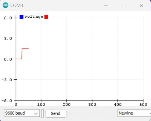
In the Tools section, you can enable either Serial Monitor or Serial Plotter to see the data.
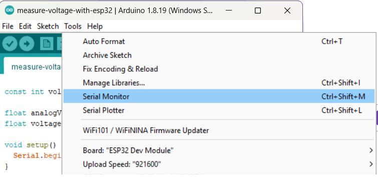
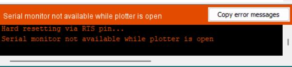
Please note that you can only use one of them at a time.
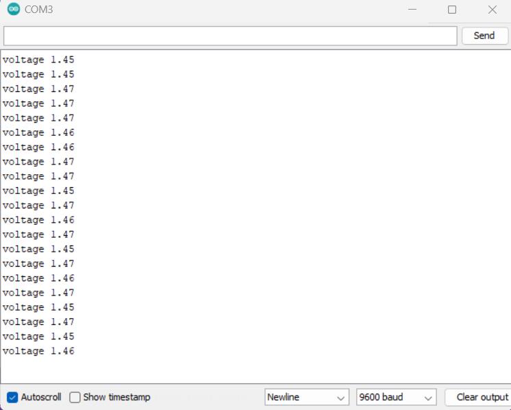
You can see the plotter or the logs show the values every time you touch the voltage probes to the battery’s positive and negative
Switching to Visual Studio CodeCopy permalink to clipboard
Arduino IDE is a reasonably good to start with. But if you want to take your ESP32 development a bit more seriously, then you will need to switch to VSCode as soon as possible.
You need to install the VScode, if you don’t have it yet by following either Our Guide for Windows 11 or just a general Microsoft Guide
Once you have that sorted, please make sure to install Platform IO extension following Their installation guidelines
Then, all you will need is to start a new project, copy the same code as above and just make sure that you are including the Arduino header at the top of the main.cpp
#include <Arduino.h>You can Build and Upload your code and will get the same results. There is no Serial Plotter here but there is a Serial Monitor so you can see your data in logs
Switching to Kasia IoT as your ESP32 WiFi LibraryCopy permalink to clipboard
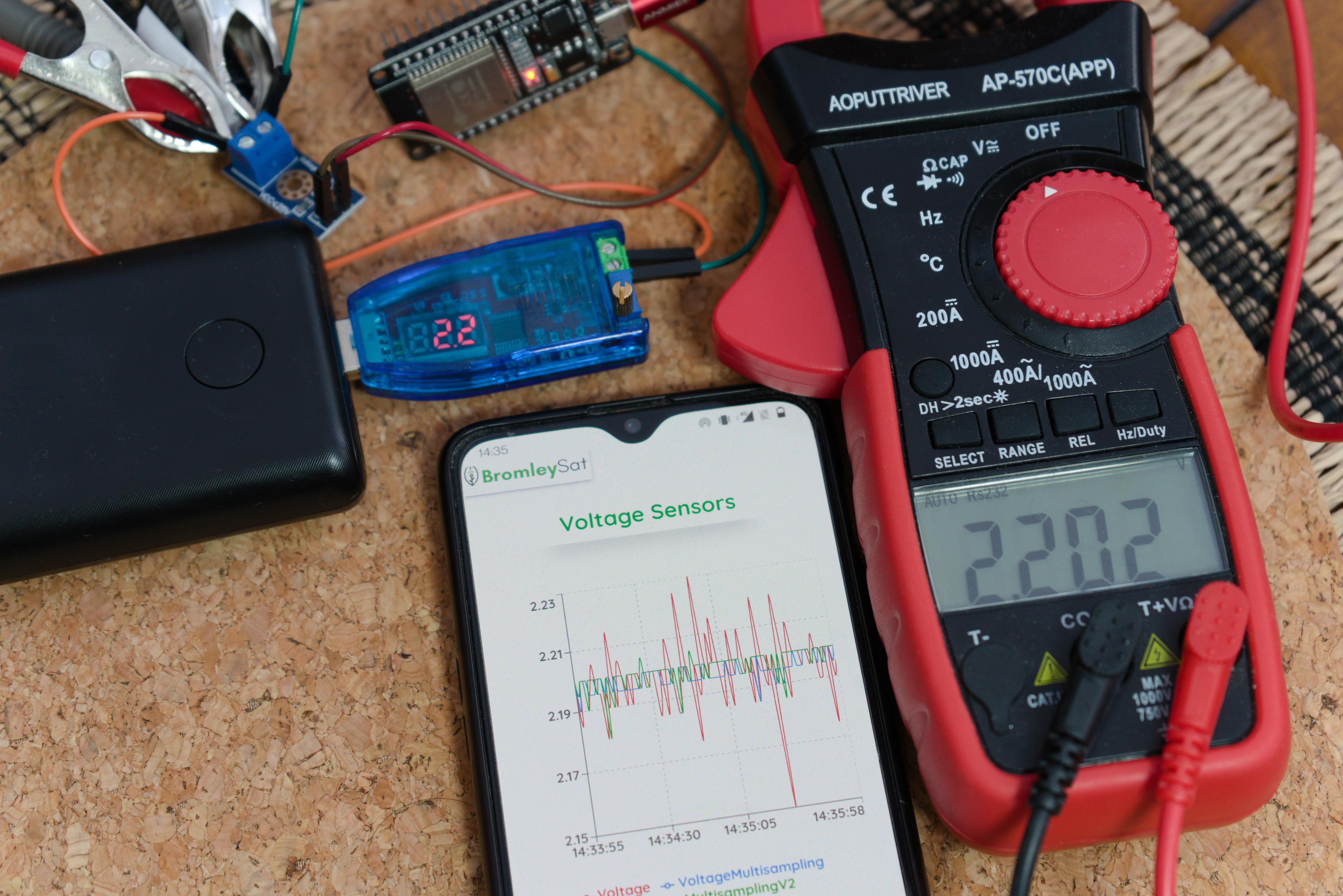
For all of our ESP32 development and testing, we use our Kasia Framework. This allows us to access the data via WiFi and not have to have our devices constantly connected to a laptop. As you can see in the image below, once the code is uploaded to the ESP32 you can use any 5V power supply and view the data from your phone, tablet or a laptop/Mac that is connected to the same network.
This tutorial uses this approach, but you don’t have to and can skip to the next section by clicking here
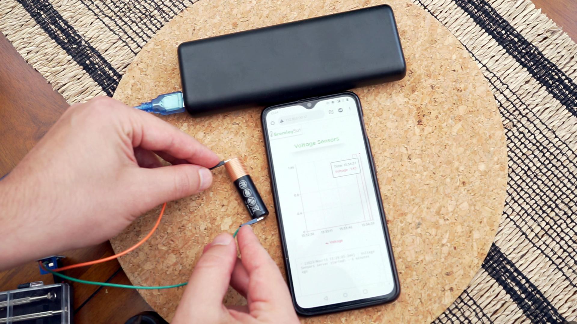
ESP32 Measuring Battery Voltage with Kasia IoT
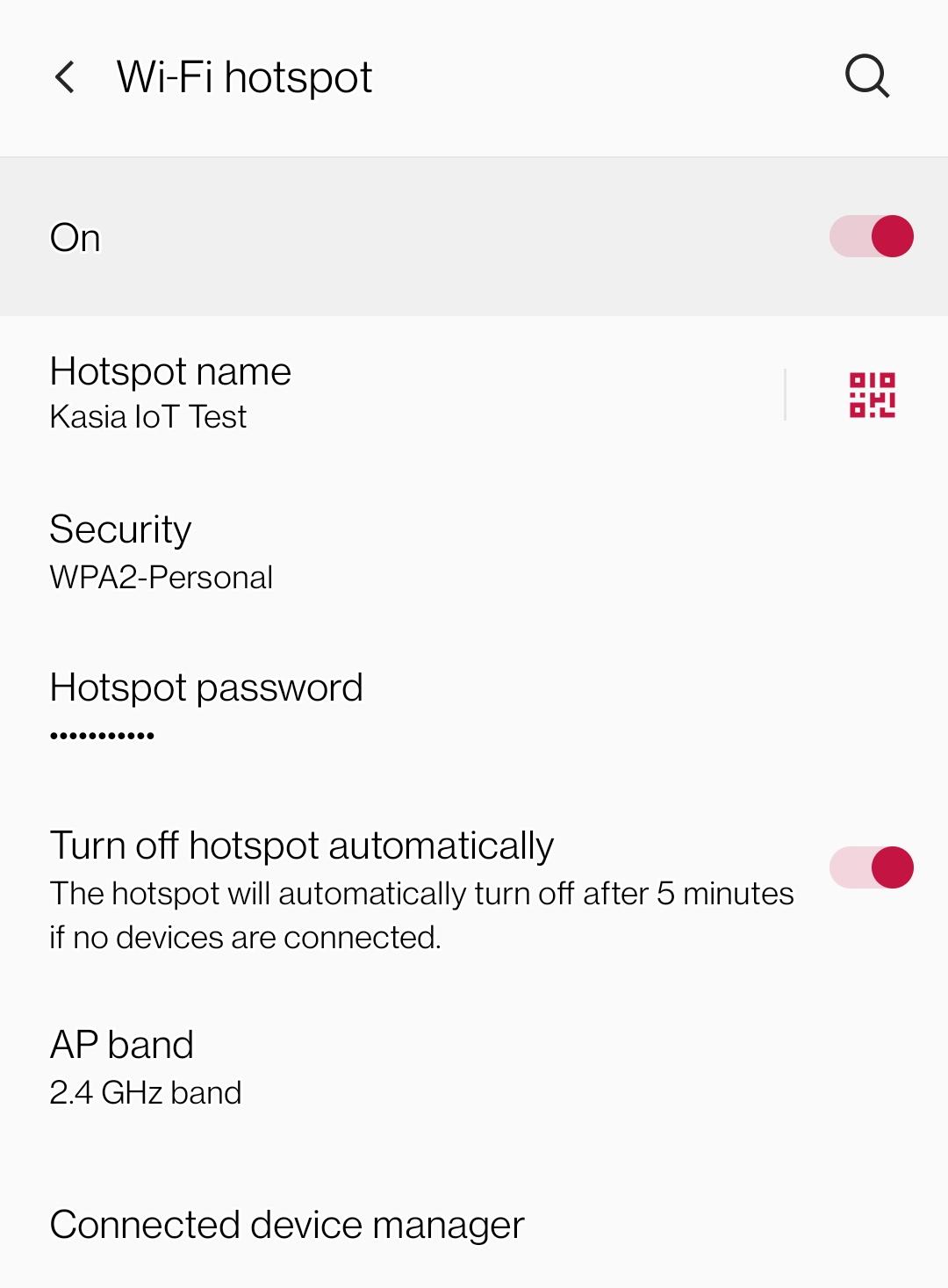
You can of course use the same WiFi that you use on your Laptop/Mac or if you prefer rather than providing your very secret home or office WiFi credentials, you can setup a Mobile device hotspot.
Create a temporary network name and password so that you can change both of these after your tests Overall we prefer to use mobile hotspot, since it allows us to access device data without having it close to any laptop.
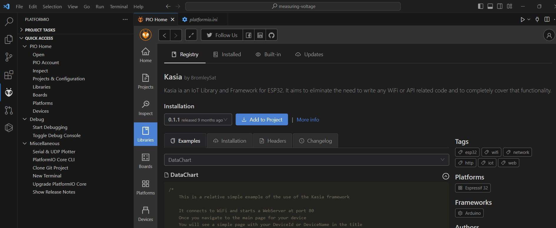
You then need to install our Kasia library by either using Platform IO library manager:
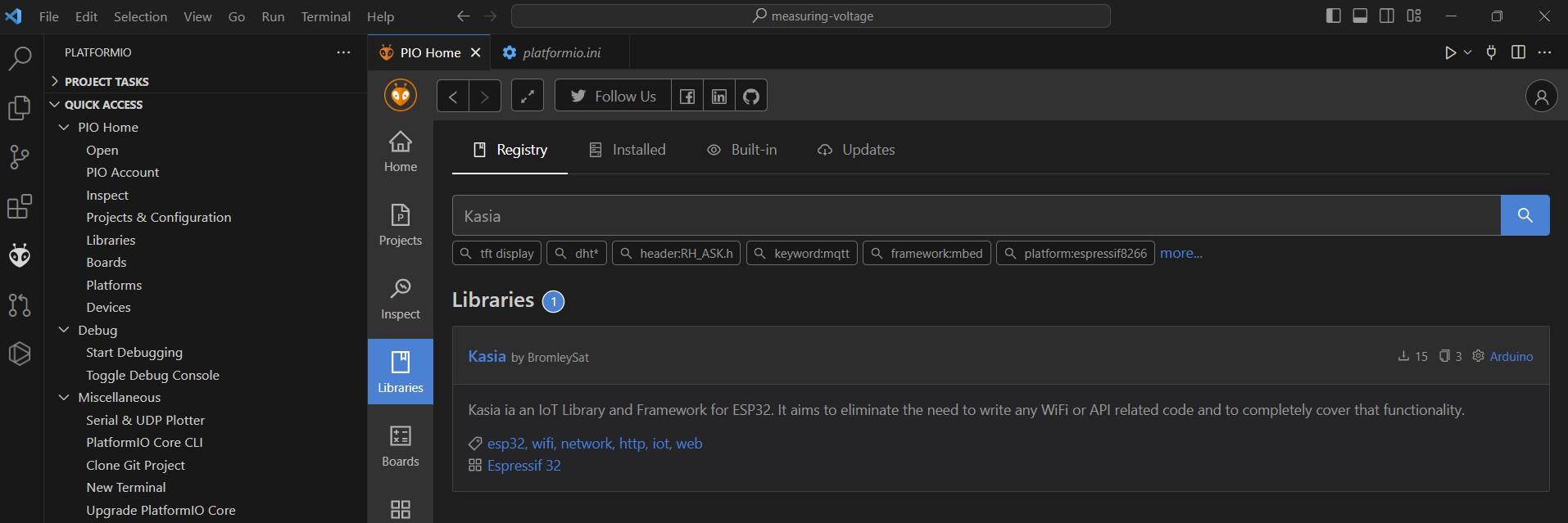
Then select it by clicking on the library name. You should see the details and can click ’Add to Project’
Or by installing it with Platform IO CLI:
pio pkg install --library "bromleysat/Kasia"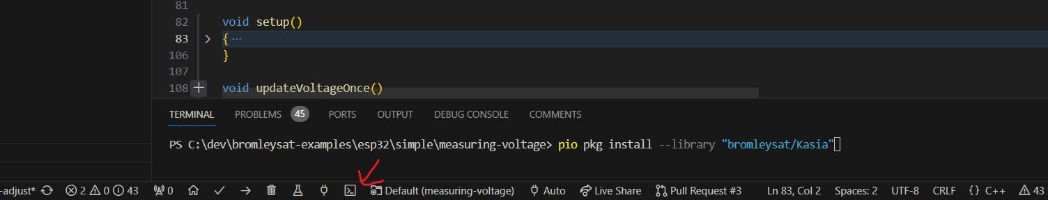
Once the Kasia library is installed, you will need to change the header at the top of your main.cpp from
#include <Arduino.h>to:
#include <Kasia.h>At the beginning of your startup code you will need to bind our voltage data with this line of code:
kasia.bindData("Voltage", &voltage);Enable Kasia IoT web server with:
kasia.start("Voltage Sensors", 9600, "<Your-WiFi-SSID>", "<Your-WiFi-Password>");You should also remove Serial.print lines, since they are now redundant and your code should end up looking similar to this:
#include <Kasia.h>
const int voltagePin = 32;
float analogValue = 0;
float voltage = 0;
void setup()
{
kasia.bindData("Voltage", &voltage);
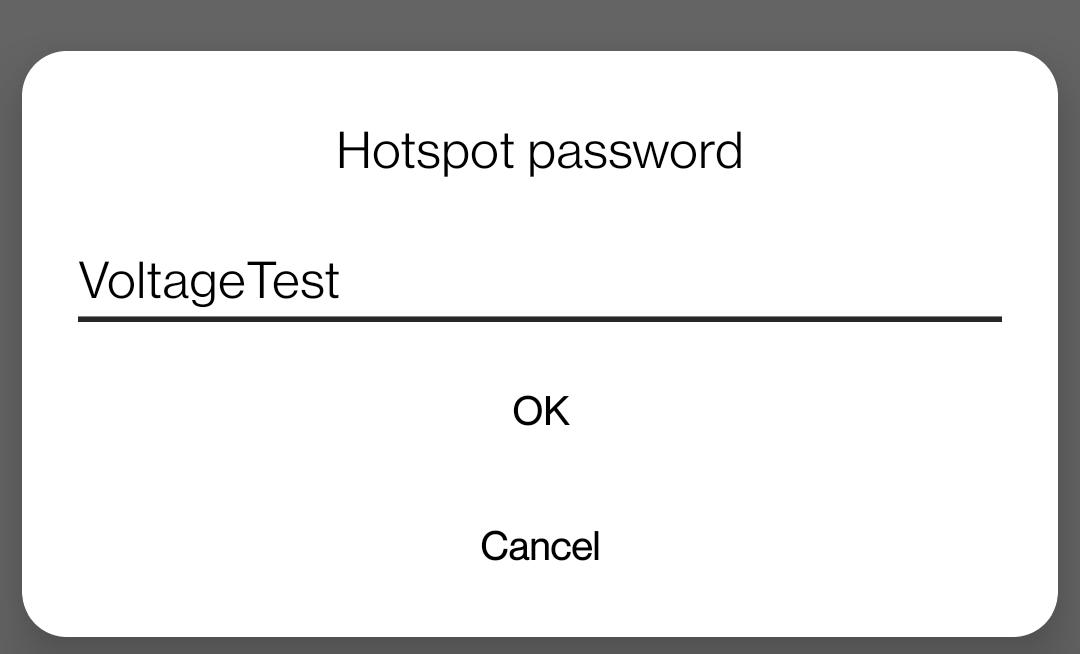
kasia.start("Voltage Sensors", 9600, "Kasia IoT Test", "VoltageTest");
}
void loop()
{
analogValue = analogRead(voltagePin);
voltage = map(analogValue, 0, 4095, 0.0, 2500.0); // deliberate mistake ;)
voltage /= 100;
delay(500);
}You can now upload the code to your device and look at the Serial Monitor of the Platform IO to see the local IP that should be assigned to the device once successfully connected to WiFi
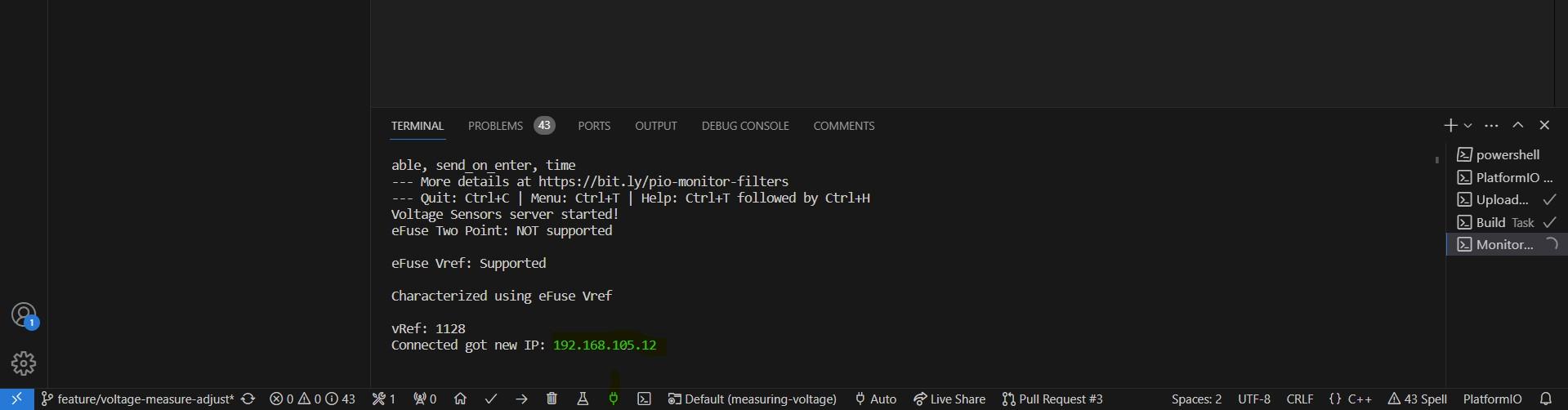
Once you get this IP you can type it in your mobile device’s browser and/or connect your Laptop/Mac to the same hotspot and then access it there as well
This way you will see the same voltage data in your browser whenever you test anything with your voltage probes
This is also useful when you need to plot multiple data points and compare values side by side. If you are interested in using this framework for your development you can find more details and relevant links on the Kasia IoT Project Page
Reading voltage from potentiometerCopy permalink to clipboard
At the beginning before we start , I would like to point something out. It is about small differences between different ESP32 development kits.
Great Success! Right?Copy permalink to clipboard
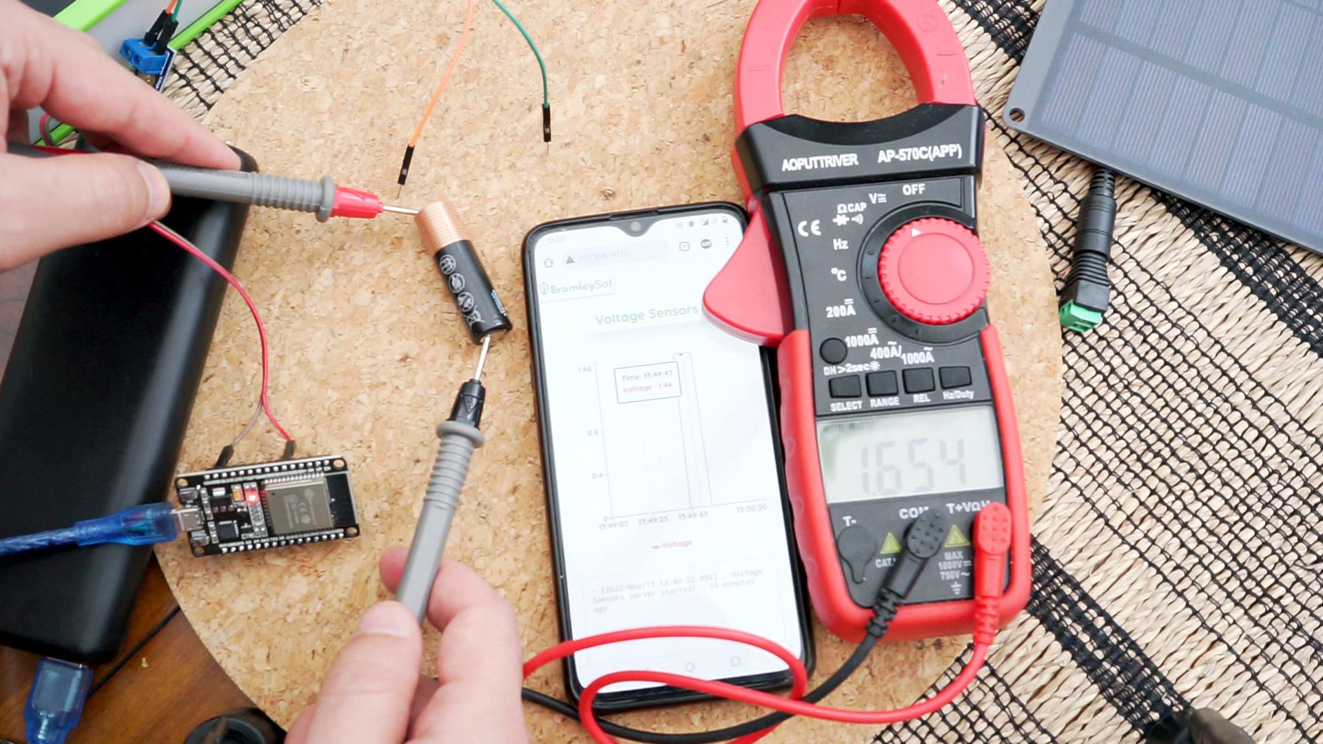
This is the point where most tutorials that we have seen out there stop. But in fact the voltage readings that we were getting for the battery are quite a bit off. We were reading 1.44V while the actual voltage is 1.654V as confirmed by the reading from the multimeter
Adjusting for 3.3V chipCopy permalink to clipboard
It is a common mistake to get confused with what it says on the actual voltage divider or ’voltage sensor’, as it is often described, and use the 25V as the upper limit of what we are expecting to measure. This is of course incorrect for ESP32s as they are 3.3V systems and we should only ever expect to measure: 3.3 * 5 = 16.5V
Voltage Sensor Zoomed In
This is very easy to correct and we change one line from:
voltage = map(analogValue, 0, 4095, 0.0, 2500.0); To:
voltage = map(analogValue, 0, 4095, 0.0, 1650.0); //<== corrected Now that this is corrected we can retest again and the results should be much better. Right?
Well not quite, they are now even further from the accurate value than before. In fact, we are getting 0.95V on average
So lets try something else, there are other articles online that suggest scaling the analog value in a different way and instead of
voltage = map(analogValue, 0, 4095, 0.0, 1650.0); //<== corrected We should do something like:
voltage = analogValue * 3.3 / 4095 * 5When we try this approach, the result is identical. 0.95V on average when the actual value is 1.655V ¯\_(ツ)_/¯
ESP32 ADC CalibrationCopy permalink to clipboard
As explained in the manufacturer’s documentation: ’Per design the ADC reference voltage is 1100 mV, however the true reference voltage can range from 1000 mV to 1200 mV amongst different ESP32s.’
Every device that we have worked with so far was factory calibrated and we could read the eFuse Voltage Reference with this code:
static void check_efuse(void)
{
  // Check if TP is burned into eFuse
  if (esp_adc_cal_check_efuse(ESP_ADC_CAL_VAL_EFUSE_TP) == ESP_OK)
  {
    logInfo("eFuse Two Point: Supported\n");
  }
  else
  {
    logInfo("eFuse Two Point: NOT supported\n");
  }
  // Check Vref is burned into eFuse
  if (esp_adc_cal_check_efuse(ESP_ADC_CAL_VAL_EFUSE_VREF) == ESP_OK)
  {
    logInfo("eFuse Vref: Supported\n");
  }
  else
  {
    logInfo("eFuse Vref: NOT supported\n");
  }
}
Then rather that using that adjusted voltage reference value to correct our calculations, we can simply use the function that they have provided here
voltageRaw = esp_adc_cal_raw_to_voltage(adcReading, adcCharacteristics); And of course we will need to get the adcCharacteristics from a previous call to another function
  // Characterize ADC
  adcCharacteristics = (esp_adc_cal_characteristics_t *)calloc(1, sizeof(esp_adc_cal_characteristics_t));
  esp_adc_cal_value_t val_type = esp_adc_cal_characterize(unit, atten, width, DEFAULT_VREF, adcCharacteristics);
In our experience, it is best to use Espressif’s functions to calculate voltages. ESP32 uses internal reference voltage to measure external voltages and it can vary between different devices.
All of the devices that we have tested so far were calibrated during production and the adjusted reference voltage was, as they put it, ’burned into eFuse BLOCK0 during factory calibration.’
You can immediately see the difference with the potentiometer voltages being read side by side:
Let us try the same code with the battery
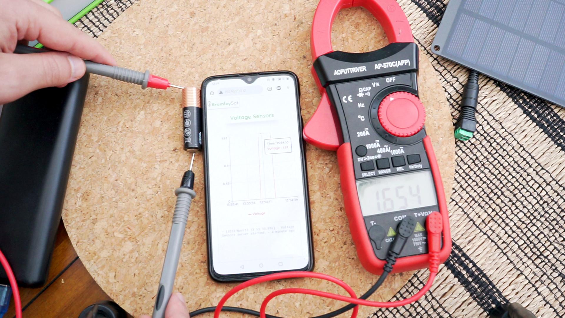
ESP32 measuring battery voltage with better accuracy as 16.5V
We are getting 1.67V on ESP32 and 16.5 on the multimeter. Still a bit too high, but so much closer to the expected value. At this stage this is already a usable measurements, but we will not want to stop here in terms of maximising the measurement accuracy
Reducing ADC NoiseCopy permalink to clipboard
MultisamplingCopy permalink to clipboard
Multisampling Improved AlgorithmCopy permalink to clipboard
Multisampling is a great technique to improve the measurement accuracy, but we do not always get the luxury of waiting multiple milliseconds for a results. This is especially an issue when our code has to react near instantaneously to fast changing voltage in a buck/boost converter setup.
We suggest an algorithm that collects all the samples, sorts them by value and then takes the middle one. We effectively use Median instead of Mean and the result is similar, but crucially the number of samples required to achieve the same level of accuracy is much less.
We compare 90 sample size mean/average multisampling with 10 sample size median measurements and you can see the comparison results before. They still include the single read fast measurements that are much move volatile
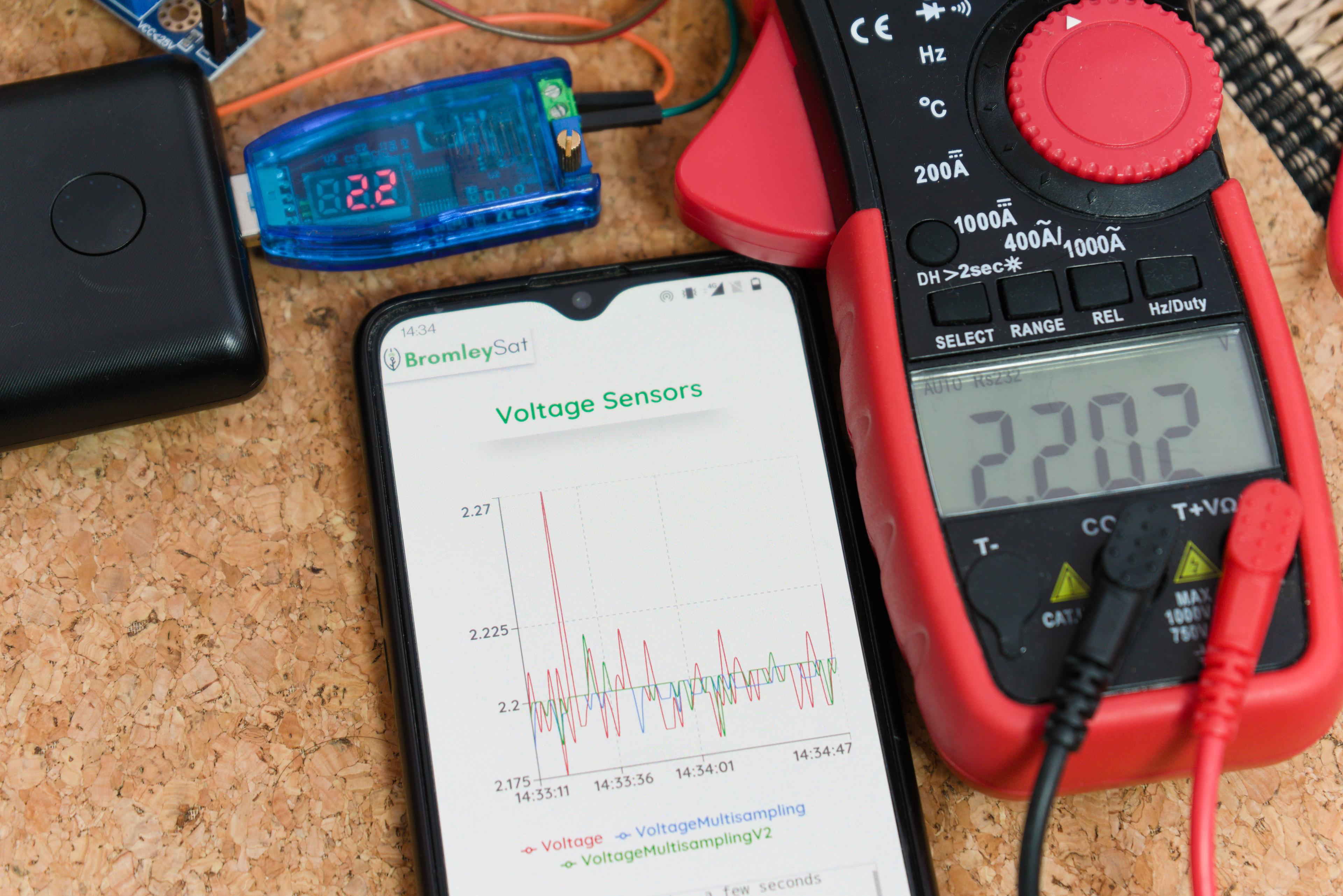
ESP32 improved accuracy and measurement speed with multisampling V2 algorithm
We have noticed that single read measurements sometime end up with very large spikes, and would expect the average calculations to be disproportionally affected by those extreme values. Hence, median measurements eliminate extreme values and we need fewer samples and in this case the measurement speed is about 3X faster
How can we improve precision even furtherCopy permalink to clipboard
Improved Voltage DividerCopy permalink to clipboard
Auto calibrationCopy permalink to clipboard
Voltage Divider MultiplierCopy permalink to clipboard
ESP32 can only measure up to 3.3V out of the box and to increase the voltage measuring range, we will need to use a Voltage Divider. That works with the following formula:
Vout = (Vs * R2 )/(R1 + R2)In this case we are using a standard voltage divider that is often used with an Arduino or an ESP32 and our resistors are:
R1 = 30kΩ
R2 = 7.5kΩ
Substituting those numbers in the voltage divider equation
Vout = (Vs * 7.5 )/(30 + 7.5)Gives us 1 to 5 ratio of measured to actual voltage